| Parameters |
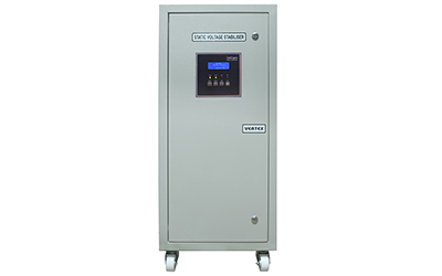
Single Phase SVS |
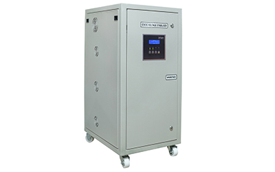
Three Phase SVS |
| Construction |
Indoor Purpose |
Indoor Purpose |
| Type of Design |
IGBT Based PWM technology Static Servo Stabiliser with O/P sensing feed-back system |
IGBT Based PWM technology Static Servo Stabiliser with O/P sensing feed-back system |
| NA |
Independent Phase Control, Suitable for Unbalanced Loads |
| Type Of Cooling |
Aircooled |
Aircooled |
| Input Voltage Range |
I/P: ±15 % / ±20 % / ±25 % of the designed O/P voltage |
I/P: ± 15 % / ± 20 % / ± 25 % of the designed O/P voltage |
| Input Frequency |
47 Hz - 65 Hz |
47 Hz - 65 Hz |
| Output Voltage |
230 V 1-Phase Settable - 220/240 V (L - N) |
415 V 3-Phase Settable - 380/400 V (L - L) |
| Output Voltage Regulation |
± 1 % |
± 1 % |
| Control Design |
IGBT based PWM technology with Digital Signal Processor (dsPIC) Control System |
IGBT based PWM technology with Digital Signal Processor (dsPIC) Control System |
| Waveform Distortion |
NIL (Output Waveform same as Input Waveform) |
NIL (Output Waveform same as Input Waveform) |
| Effect of Load PF on O/P Voltage |
NIL |
NIL |
| Correction Speed |
20000 V/ Sec max |
20000 V/ Sec max |
| Efficiency |
> 97% |
> 97% |
| High Voltage / Low Voltage Cut-Off |
Input High / Low Voltage Cut-off to trip Output Relay / Contactor
Output High
/ Low Voltage Cut-off to trip Output Relay / Contactor |
Input High / Low Voltage Cut-off to trip Output Relay / Contactor
Output High
/ Low Voltage Cut-off to trip Output Relay / Contactor |
| Short Circuit Protection |
MCB (OR) MCCB at Input |
MCB (OR) MCCB at Input |
| Output Overload Protection |
Electronic Overload cut-off (CT based) |
Electronic Overload cut-off (CT based) |
| Phase Reversal Protection |
NA |
Built-in |
| Single Phasing Prevention |
NA |
Built-in |
| Display Type |
LED Display |
20 x 4 Line Backlight LCD Display |
| Parameters Displayed |
I/P & O/P Voltage
O/P Amps |
I/P & O/P Voltage (L-L & L-N)
O/P Amps (R-Y-B), % Load,
kVA,
Hz, N-E Volts |
| Front Panel Indications |
LED Indication for -
Input
Output |
LED Indication for -
Input Normal
Output Normal
Phase
Fault
Overload
|
| Event Recorder |
- |
Error Log for Fault Condition
(100 events log Storage) |
| Front Panel User Interface |
Menu / Set / Start / Stop |
Menu / Start / Stop / Log |
| Stabiliser “ON/OFF” Operation |
Manual Mode - Start / Stop
Auto Mode - User Settable |
Manual Mode - Start / Stop
Auto Mode - User Settable |
| Input / Output Connection |
Input / Output Terminal Plate (Nut-Bolt arrangement) |
Input / Output Terminal Plate (Nut-Bolt arrangement) |
| Emergency Manual Bypass |
Optional |
Built-in |
| System Auto Bypass |
System bypass in case of IBGT current is more than the set value to protect the IGBT
Controller |
System bypass in case of IBGT current is more than the set value to protect the IGBT
Controller |
| Output Relay / Contactor |
Built-in |
Built-in |
| Surge Protection Device (SPD) |
Class-B 25 kA |
Class-B 25 kA |
| EMI / RFI Filter |
Optional |
Optional |
| Operating Temperature |
0° C to 50° C |
0° C to 50° C |
| Standard kVA Ratings |
3 kVA to 25 kVA |
10 kVA to 200 kVA |